Design and production of a practical electronic counting device
Source: InternetPublisher:supremeOne Keywords: electronic counting Updated: 2023/12/11
1. Working principle
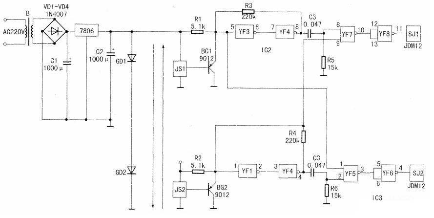
The power supply part of this circuit uses the most common 220V step-down bridge rectifier and voltage stabilizing block to output a 6V DC voltage to provide power for the whole machine. As shown in the circuit diagram, when there is no material passing through the belt conveyor, the light of laser tubes GD1 and GD2 is not blocked, the receivers JS1 and JS2 both work, their emitters maintain low voltage, and the gate circuit and counter do not work. When the cans are put into the furnace, the light emitted by GD2 is blocked first, the receiver JS2 stops working and outputs a high level, and the transistor BG2 cuts off and outputs a high level. This voltage is divided into two channels, one channel is given to the ⑨ pin of NAND gate YF7, and the other channel is inverted twice through NAND gates YF1 and YF2 to charge capacitor C4. When the can bottle continues to move forward and blocks the light emitted by GD1, the receiver JS1 stops working and outputs a high level, and the transistor BG1 cuts off and outputs a high level. It is also divided into two channels: one channel charges the capacitor C3 through two inversions of NAND gates YF3 and YF4, and then generates a high level on pin ⑧ of YF7. YF7 outputs a low level, which is inverted by NAND gate YF8. The (11) pin of YF8 outputs high level, causing the forward counter SJ1 to count once. At the same time, another high level output by transistor BG1 is also added to pin ① of YF5. However, due to the small capacitance of C4, the high level originally lost to pin ② of YF5 by BG2, YF1, and YF2 has passed. , so the ① and ② pins of YF5 present high and low levels, YF5 outputs high level, and after the inversion of YF6, SJ2 does not work.
In the same way, when the cans come out of the oven, the laser tubes GD1 and GD2 will be blocked successively, causing the receivers JS1 and JS2 to work successively, and finally the reverse counter SJ2 will work and the forward counter SJ1 will not work.
2. Production
1. It is best to use laser diodes for GD1 and GD2. If ordinary infrared light-emitting diodes are used, malfunctions may easily occur due to their strong scattering properties. It can be directly modified with a commercially available children's laser toy, which is convenient and cheap; in addition. CD4009 can be used for IC2, and CD4011 can be used for IC3.
2. A 50-100cm shaped steel plate should be added to the counting belt conveyor to ensure that the cans pass through the counting device in a single row, so as to avoid missing counting due to overlapping cans and bottles. At the same time, the laser tube can also be installed by drilling holes. on top.
3. The installation height of the laser tube should be based on the height of the can bottleneck, and the installation distance between the two laser tubes should be slightly smaller than the bottleneck width of the can bottle.
4. The two transistors BG1 and BG2 are wearing parts and should be inspected frequently.

- LED acceleration and deceleration motion display composed of CD4017
- Fire safety evacuation emergency signs
- LED Signage with RS232 Port Operation Guide
- Design and production of a practical electronic counting device
- Driving circuit for driving light-emitting diodes by IR53HD420
- Use NE555 to make a touch self-extinguishing table lamp
- Lighting sound-activated switch circuit using thyristors Part 3
- Simple light-controlled street light circuit (7)
- Economical and practical delay light circuit
- Two-way electronic music doorbell circuit
- 555 timer disconnection photoelectric isolation safety protection circuit
- Breathing light circuit diagram designed by NE555
- Micromotor pedal speed regulator circuit and improvement
- The battery fast charging circuit is composed of BQ2002 battery fast charging control integrated circuit
- Use 555 to make DC-DC boost circuit


 京公网安备 11010802033920号