Working principle and function of half-bridge drive circuit
Source: InternetPublisher:狂妄火龙果 Keywords: Amplifiers power supplies and other power circuits Updated: 2020/11/11
The role of the half-bridge drive circuit:
The main function of the half-bridge drive circuit is to generate an AC trigger signal through the power tube, thereby generating a large current to further drive the motor. Different from the single-chip microcomputer driver, the single-chip microcomputer has limited driving capabilities and is generally only used as a driving signal.
The working principle of the half-bridge drive circuit:

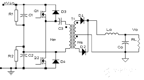
Basic topological circuit diagram of half-bridge circuit
Capacitors C1 and C2 and switching tubes Q1 and Q2 form a bridge. The diagonal line of the bridge is connected to the primary winding of transformer T1, so it is called a half-bridge converter. If C1=C2 at this time, then when a certain switch tube is turned on, the voltage on the winding is only half of the power supply voltage.
The working process of the circuit is roughly as follows:
Referring to the basic topological circuit diagram of the half-bridge circuit, Q1 is turned on and Q2 is turned off. At this time, the voltage applied to both ends of the transformer is half of the bus voltage, and energy is transferred from the primary side to the secondary side.
Q1 is turned off and Q2 is turned off. At this time, the two secondary windings of the transformer are in a short-circuit state due to the simultaneous freewheeling of the two rectifier diodes. The primary winding is also equivalent to a short-circuit state.
Q1 is off and Q2 is on. At this time, the voltage applied at both ends of the transformer is basically half of the bus voltage, and energy is transferred from the primary side to the secondary side. The two diodes on the secondary side complete the commutation.
Several issues that should be paid attention to
Bias problem
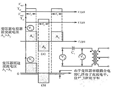
Reason: Since the potential of the two capacitor connection point A floats with the conduction of Q1 and Q2, it can automatically balance the volt-second value of each transistor switch. When the floating does not meet the requirements, it is assumed that Q1 and Q2 have different The switching characteristics of The unbalanced volt-second value is due to the Q1 turn-off delay.
If such an unbalanced waveform is used to drive a transformer, a magnetic bias phenomenon will occur, causing the core to saturate and generate an excessive collector current of the transistor, thus reducing the efficiency of the converter and causing the transistor to lose control or even burn out.

The working waveform diagram of connecting a capacitor in series with the primary side of the transformer
Solution: Add a series capacitor C3 to the primary coil of the transformer, then the DC bias voltage proportional to the unbalanced volt-second value will be filtered out by the secondary capacitor, so that during the conduction period of the transistor, the voltage volt-second will be balanced value to achieve the purpose of eliminating bias magnetism.
Problems in selecting two capacitors used as bridge arms:
From the perspective of the half-bridge circuit structure, when selecting the two capacitors C1 and C2 on the bridge arm, the voltage balancing problem of the capacitor needs to be considered. Try to choose the capacitor with C1=C2. Then when a certain switch tube is turned on, the voltage on the winding It is only half of the power supply voltage to achieve the voltage equalization effect. Generally, a resistor (R1 and R2 in the schematic diagram) must be connected in parallel at both ends of the two capacitors and R1=R2 to further meet the requirements. At this time, select the resistance value You need to pay attention to derating when adjusting the power. At this time, the function of capacitors C1 and C2 is to automatically balance the volt-second value of each switch tube (the difference from C3: C3 filters out the DC component that affects the volt-second balance).
pass-through problem
The so-called shoot-through is the phenomenon that Q1 and Q2 are turned on at the same time at a certain moment, which will form a short circuit.
solution
The maximum value of the driving pulse width can be limited so that the conduction angle does not cause shoot-through.
The problem can also be solved topologically by using cross-coupling to close the circuit. When one tube is turned on, the other tube is driven in a closed state. The sealing is not canceled until the previous tube is turned off, and the subsequent tube has the possibility of being turned on. This automatic blocking has the advantage of automatically adapting to storage time and parameter distribution, and can be used at full duty cycle.

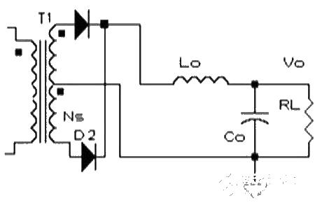
The secondary side is a full wave circuit

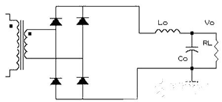
The secondary side is a full bridge circuit
The selection of the two circuits mainly considers the following two points:
1. Depending on the output voltage, consider the safety of the tube;
2. The problem of power loss is mainly the loss of switching tube and secondary winding;
Driving problems of half-bridge circuit:
1. Primary side coil overload limitation: provide an independent current limit for the primary side power tube;
2. Soft start: When starting, the pulse width should be limited so that the pulse width slowly rises in the first few cycles of startup;
3. Magnetic control: The control transistor driving pulse width is equal to ensure that the positive and negative magnetic fluxes are equal and no bias is generated;
4. Prevent pass-through: control the upper limit of duty cycle to reduce;
5. Voltage control and isolation: The circuit must be closed-loop controlled, and isolation can be a photoelectric isolator, transformer or magnetic amplifier, etc.;
6. Overvoltage protection: Usually the switching pulse of the converter is blocked for overvoltage protection;
7. Current limit: The current limit is installed on the input or output circuit and takes effect when a short circuit occurs;
8. Low input voltage protection: It is stipulated that it can only be started at a voltage high enough to achieve good performance;
9. In addition, appropriate auxiliary functions must be provided: such as inrush current limiting and output filtering links.
Driving characteristics of half-bridge circuit:
1. The upper and lower bridge arms do not share the same ground, that is, the switching tubes of the primary circuit do not share the same ground.
2. Isolate drive.
- ISO113 circuit that can reduce power consumption
- BA6104 five-digit LED level meter driver integrated circuit basic application circuit
- Visible laser digital control modulation driver
- Driving circuit that controls LED brightness using PWM signal
- Parallel DC regulated power supply circuit diagram
- A small and easy-to-make fast charger
- A novel and practical DC low voltage stabilized power supply
- Production of backup power supply for cordless phone
- A low-cost, high-reliability battery charger for electric vehicles
- How to Select Modular EMI Filters for AC-DC Converters
- High performance broadband GaN power amplifier
- Op amp driving LEDs
- Fiber optic transceiver circuit diagram
- Cascade MMIC amplifier circuit diagram
- LTC2053 thermocouple amplification circuit diagram
- KBC-Ⅱ type programmable power circuit
- Parallel power op amp
- Parallel power op amp
- Single Supply Op Amp Applications
- High frequency impedance matching amplifier


 京公网安备 11010802033920号