|
The OP
Published on 2024-3-5 21:19
Only look at the author
This post is from RF/Wirelessly
| ||
|
Personal signature
射频【放大器】 |
||
- 【Posts】"This knowledge is not too cold" Understanding antenna multiplexers
- 【Posts】Smartphone Antenna Tuner ESD Protection: What You Must Know
- 【Posts】"This knowledge is not too cold" Exploring ultra-wideband technology
- 【Posts】Comprehensive understanding of antennas, the knowledge you don’t know!
- 【Posts】Quectel BC28 NB module antenna debugging problem
- 【Posts】Misunderstandings about the Interference Resistance of Monopole and Dipole Antennas
- 【Posts】I would like to ask you, what are the conditions for radio waves to be generated and emitted from the antenna?
- 【Posts】How to simulate a circuit with an antenna?
- 【Download】Analog Switch and Multiplexer Basics
- 【Download】How to design a good internal antenna? Many people still don\'t understand how to design a good internal antenna.
- 【Download】Let you understand the various cost data of the antenna factory
- 【Download】Built-in antenna ----------- You can learn more about it
- 【Download】Basic knowledge and application of antenna
- 【Download】Microwave technology and antenna knowledge
- 【Download】Basic knowledge of antennas
- 【Download】Antenna Basics Lecture
- 【Design】Power Multiplexer Circuit
- 【Design】NCP3901GEVB: Dual input, single output power multiplexer
- 【Design】GPSMUX: GPS Multiplexer
- 【Design】ADG732 multiplexer
- 【Design】USB Type-C and USB PD Controller Power Switch/High-Speed ??Multiplexer Reference Design
- 【Design】VGA 8:1 Multiplexer Reference Design Using the MAX4885
- 【Circuits】FMA9901A FM ??broadcast dedicated antenna
- 【Circuits】Amplification-hybrid antenna amplifier circuit
- 【Circuits】Single tube TV antenna amplifier circuit
- 【Circuits】Single tube TV antenna amplifier
- 【Circuits】Simple but effective shortwave antenna amplifier
- 【Circuits】Production of TV antenna amplifier
- 【Articles】ADI Basics Tutorial: Analog Switch and Multiplexer Basics
- 【Articles】FM DX Antenna Basics
- 【Articles】Antenna Basics
- 【Articles】Basic knowledge of magnetic antenna and intermediate frequency transformer
-
#ThisKnowledgeisNotCool# series updated - Learn about antenna multiplexers
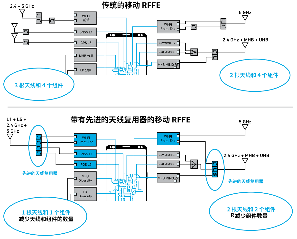
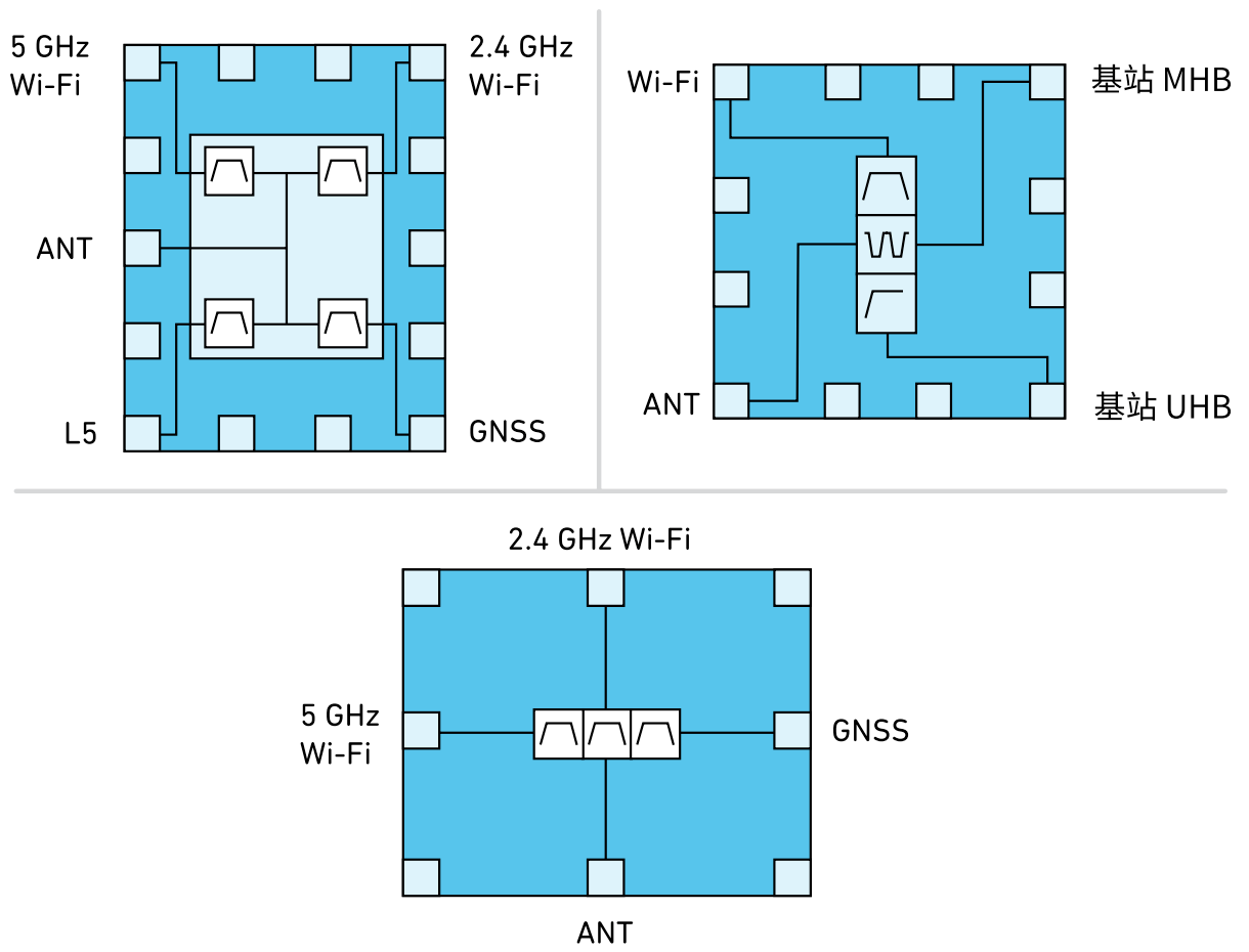
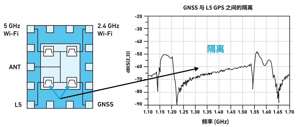
#Thisknowledgeisnottoocold#UnderstandtheantennamultiplexerManufacturerstodayfaceanimportantarchitecturaldecisionAlternatively,theycanchoosetouseanewalternative:antennamultiplexers,whichreducetheneedtoaddantennasandmeetcoexistencefilteringan ...
-
\"This knowledge is not too cold\" Exploring ultra-wideband technology
@@Thisknowledgeisnottoocold@@Exploreultra-widebandtechnologyThisarticleexplainshowpositioningtechnologygotitsstartandhownewdevelopmentscontinuetochangeourworldHowpositioningtechnologyischangingtheworldBelieveitornot,just20yearsago,thepublic ...
-
Is there a common anode digital tube with the same package as ARK SR420361K?
Iwouldliketoasktheexperts,isthereacommonanodedigitaltubewiththesamepackageasARKSR420361K?Thankyou
- Bluetooth module parameters - transmit power, receive sensitivity, air rate, what equipment can be used to test these parameters more accurately...
- The headlight step-down chip already has a DIM enable terminal to control the on and off of the headlights, so why add a circuit to control the BAT+ supply...
- 17 kinds of component PCB packaging illustrations, beautiful
- Three-port DC-DC converter (Problem C)
- Parts information management system Musecad CircuiteXpert - solves parts usage, library management, auditing, plug-in failure, BOM...
- 14. Purgatory Legend-FIFO Battle
- MV-VS Series 1394 High Resolution Industrial Digital CCD Camera
EEWorld Datasheet Technical Support
-
"Cross-chip" quantum entanglement helps build more powerful quantum computing capabilities
IBM scientists have achieved "cross-chip" quantum entanglement - successfully entangled two "Eagl
-
Ultrasound patch can continuously and noninvasively monitor blood pressure
A research team at the University of California, San Diego, has developed an innovative wearable
-
Europe's three largest chip giants re-examine their supply chains
At the Electronica 2024 CEO Roundtable held just last week, the CEOs of three chip giants, Infine
- It is reported that Kioxia will be approved for listing as early as tomorrow, and its market value is expected to reach 750 billion yen
- The US government finalizes a $1.5 billion CHIPS Act subsidy to GlobalFoundries to support the latter's expansion of production capacity in the US
- SK Hynix announces mass production of the world's highest 321-layer 1Tb TLC 4D NAND flash memory, plans to ship it in the first half of 2025
- UWB is a new way to use it in cars. Can wireless BMS also use it?
- Filling the domestic gap! China Mobile, Huawei and others jointly released the first GSE DPU chip
- Samsung Electronics NRD-K Semiconductor R&D Complex to import ASML High NA EUV lithography equipment
- Apple reveals the secret of its own chip success: competitors can't use the latest cutting-edge technology
-
CERTIFICATION TEST OF MOTOROLA GSM BTS ICI
Exam Outline 1. Exam Purpose To certify the HORIZEN MACRO1800 and 900 base station installation and commissioning qualif ...
-
A boy confessed his love to a girl at KFC [Repost]
Yesterday I went to KFC. The couple behind me ordered a lot of food and then sat next to me. After sitting down, t ...
-
Chip Packaging Overview
Chip packaging 1. DIP dual in-line package DIP (Dual In-line Package) refers to an integrated circuit chip packa ...
-
MATLAB APP Designer serial port debugging tool writing
This post was last edited by lb8820265 on 2019-5-9 23:11 Previously, we introduced two ways to use VC6 to make serial ...
-
How to choose a DSP?
The selection of DSP can be determined based on the following aspects: 1) Speed: DSP speed is generally expressed in MI ...
-
Motor Control Basics - Principle of Timer Capturing Single Input Pulse
This post was last edited by DDZZ669 on 2021-2-28 14:58 The previous article (https://bbs.eeworld.com.cn/thread-11570 ...
-
[Discussion] I'm looking at a product recently, a 400x400 camera for car use
I don't know where the 400x400 camera with a 70mm object distance is used in cars. There are quite a few of them shipped ...
-
What are the functions of the three pins VDD, VEE and VSS in HEF4051?
687088
-
[ACM32G103RCT6 development board review] + GPIO port usage
This post was last edited by jinglixixi on 2023-12-22 20:48 As a starting point for mastering a development board, the ...
-
Python combined with LabVIEW programming (1)
Python combined with LabVIEW programming (1) Hi, uu, good evening! Where did you go for National Day? How do you feel ab ...
- Problems with STM32 and passive buzzer playing sound
- Embedded Tutorial_DSP Technology_DSP Experiment Box Operation Tutorial: 2-28 Building a Lightweight WEB Server Experiment
- OPA847IDBVR op amp domestic replacement
- AG32VF407 Test UART
- [Digi-Key Follow Me Issue 2] Chapter 1: Sharing on receiving the goods
- What model is this infrared receiver? Which model can be used instead? Thank you
- Selling brand new unopened ZYNQ 7Z020 FPGA core board
- The LORA module used in the lithium battery-powered water meter setting can save energy when 100 water meters are installed in one corridor.
- I would like to ask, when a port is set to RX0, is it necessary to set the input and output direction of this port?
- Why is this year so difficult? It’s even more difficult than during the pandemic. I’m 30 and facing unemployment. I’m so confused.
- Ask about the voltage regulator test question
- [Xiaohua HC32F448 Review] About Xiaohua Semiconductor's UART interrupt sending and PRINTF construction and redirection
- 【BIGTREETECH PI development board】 HDMI output test
- 【BIGTREETECH PI development board】+08. Audio test (zmj)
- [Xiaohua HC32F448 Review] +RTC electronic clock


 提升卡
提升卡 变色卡
变色卡 千斤顶
千斤顶