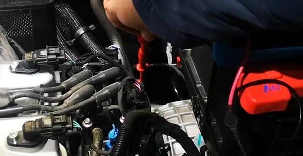
|
The OP
Published on 2020-10-4 21:30
Only look at the author
This post is from Automotive Electronics
| ||
|
|
||
-
Automobile Oscilloscope Detection of Fuel Injection Nozzle (Gasoline Engine) Waveform Signal and Analysis
ThefuelinjectorusedinautomobilesisasimplesolenoidvalveThedriverofthefuelinjectoriscomposedofatransistorandcorrespondingcircuitsinthepowercontrolsystemmodulePCMSincethedisassemblyofthefuelinjectorisverytroublesome,measuringthewaveformcanofte ...
-
Auto repair oscilloscope measurement and analysis of automobile engine cooling fan signal
ThecoolingfanofacarengineisanimportantpartofthevehiclecoolingsystemTheperformanceofthefandirectlyaffectstheheatdissipationeffectoftheengine,therebyaffectingtheengine'sperformance.Theenginecomputergeneratesadutycyclesignal(PWM)accordingtothe ...
-
GB 4824-2019 CISPR 11-2016
Industrial,scientificandmedicalequipment-Limitsandmethodsofmeasurementofradiofrequencydisturbancecharacteristics
- Which company has reflow soldering? Can you help solder some components?
- There are two main types of crystal oscillators: active crystal oscillators and passive crystal oscillators
- ST U5 development board evaluation and programming related issues (official sharing)
- Problems with ST Motor Control Workbench
- Capacitor models, selection, capacitance calculation and PCB layout
- 【Me and gui-guider①】Create a new GUI project
- Ericsson and Norway's Telenor sign global microwave transmission supply agreement
EEWorld Datasheet Technical Support
-
Nvidia's new generation Blackwell GPU is exposed to overheating problems, causing delivery delays
On November 18, local time on Sunday, The Information reported that Nvidia's new generation of Bl
-
Tata Motors acquires Pegatron's only iPhone factory in India, deepening cooperation with Apple
On November 17, Reuters reported that two sources said that Indian technology giant Tata Group ha
-
Huawei's Strategic Department Director Gai Gang: The cumulative installed base of open source Euler operating system exceeds 10 million sets
On November 15, it was reported that the first AI native open source operating system of openEule
- Wi-Fi 8 specification is on the way: 2.4/5/6GHz triple-band operation
- Vietnam's chip packaging and testing business is growing, and supply-side fragmentation is splitting the market
- Apple faces class action lawsuit from 40 million UK iCloud users, faces $27.6 billion in claims
- The US asked TSMC to restrict the export of high-end chips, and the Ministry of Commerce responded
- ASML predicts that its revenue in 2030 will exceed 457 billion yuan! Gross profit margin 56-60%
- Qualcomm launches its first RISC-V architecture programmable connectivity module QCC74xM, supporting Wi-Fi 6 and other protocols
- Problems with STM32 and passive buzzer playing sound
- Embedded Tutorial_DSP Technology_DSP Experiment Box Operation Tutorial: 2-28 Building a Lightweight WEB Server Experiment
- OPA847IDBVR op amp domestic replacement
- AG32VF407 Test UART
- [Digi-Key Follow Me Issue 2] Chapter 1: Sharing on receiving the goods
- What model is this infrared receiver? Which model can be used instead? Thank you
- Selling brand new unopened ZYNQ 7Z020 FPGA core board
- The LORA module used in the lithium battery-powered water meter setting can save energy when 100 water meters are installed in one corridor.
- I would like to ask, when a port is set to RX0, is it necessary to set the input and output direction of this port?
- Why is this year so difficult? It’s even more difficult than during the pandemic. I’m 30 and facing unemployment. I’m so confused.
- Ask about the voltage regulator test question
- [Xiaohua HC32F448 Review] About Xiaohua Semiconductor's UART interrupt sending and PRINTF construction and redirection
- 【BIGTREETECH PI development board】 HDMI output test
- 【BIGTREETECH PI development board】+08. Audio test (zmj)
- [Xiaohua HC32F448 Review] +RTC electronic clock
- Canaan K230AI Development Board Review 8--Face 3D Network, Human Key Points, License Plate Recognition, Character Recognition, Object Recognition
- Embedded Engineer AI Challenge Camp (Advanced): Deploy InsightFace algorithm on RV1106 for real-time face recognition of multiple people
- # STM32H7S78-DK Development Kit Three-week Review: Implementation and Analysis of Simple Sound Collection and Storage Using SD Card Reading and Writing
- [STM32H7R/S] Review⑧ nano edge ai studio training a model--Part 1
- [2024 DigiKey Creative Competition] A "fortune-telling" artifact based on Raspberry Pi
- New energy vehicle on-board AC slow charging and maintenance
- Embedded Engineer AI Challenge Camp (Advanced): Deploy InsightFace algorithm on RV1106 for real-time face recognition of multiple people
- I want to make a self-driving car. I saw one on Bilibili that costs 300 yuan. I am hesitant.
- [K230 Embedded AI Development Board Review] + License Plate Recognition and Billing Management
- How to deploy LVGL free graphics library on low-cost ARM platform, based on Allwinner T113-i
- 参会有好礼 | 2024 瑞萨电子MCU/MPU工业技术研讨会
- 深圳站:11月30日(周六)深圳湾万怡酒店
上海站:12月06日(周五)上海喜玛拉雅酒店
奖励设置:现金红包、螺丝刀套装或30元京东卡
- Littelfuse 新品赋能电子产品安全可靠并高效, 10+挑战等你探索!
- Littelfuse 应用赋能星球,覆盖了诸多应用痛点及解决办法,邀请工程师一起探索,解锁更多设计力!
- 了解英飞凌新品AIROC™ CYW5591x 无线MCU,答题赢好礼!
- 无线键盘鼠标套装、智能音箱、登山包、收纳包
- 下载资料赢好礼!看Vicor模块化电源解决方案如何推动创新
- 活动时间:即日起-2024年12月31日
如何参与:点击活动页内您想了解的模块,找到资料下载即可参与抽奖,活动结束后统一发奖!
- 有奖活动|英飞凌高密度双相电源模块为高性能运算平台而生
- 活动时间:即日起-12月15日
活动奖励:蓝牙音箱、氮化镓充电器套装、黑色小背包
- 本周精选下载推荐:电源管理基础Dummies
- 本周小编给大家带来一本超简单、超干货的电子书——《电源管理基础Dummies》!内容深入浅出,排版舒服简洁,分分钟能get到电源管理最核心的知识内容。
EEWorld
subscription
account

EEWorld
service
account

Automotive
development
circle

About Us Customer Service Contact Information Datasheet Sitemap LatestNews
- I want to get started with AD PCB practice, what should I do?
- I want to get started with fpga vhdl design, what should I do?
- I want to get started with FPGA quickly, what should I do?
- I want to get started with PCB design quickly, what should I do?
- I want to get started with Xilinx deep learning, what should I do?
- How to get started with high-speed PCB
- How to get started with deep learning computers
- How to get started with deep learning languages
- Application of digital twins in the industrial field
- What does universal Bluetooth pairing software mean?


 Room 1530, Zhongguancun MOOC Times Building,
Block B, 18 Zhongguancun Street, Haidian District,
Beijing 100190, China
Tel:(010)82350740
Postcode:100190
 京公网安备 11010802033920号


 提升卡
提升卡 变色卡
变色卡 千斤顶
千斤顶