Homemade Metal Detector
Source: InternetPublisher:太白金星 Keywords: Metal Detectors Updated: 2024/09/30
This is a metal detection circuit that can detect coins or metal pieces under the carpet. This small device is very suitable for DIY.
1. Preparation of components
The NPN transistor in the circuit is 9014. The amplification factor of transistor VT1 should not be too large, so as to improve the sensitivity of the circuit. VD1-VD2 is 1N4148. The resistors are all 1/8W.
The probe of the metal detector is a key component, which is an inductor coil with a magnetic core. The magnetic core can be a Φ10 radio antenna magnetic rod, cut off 15mm, and then use an insulating board or thick cardboard to make two baffles with a diameter of 20mm, dig a Φ10mm hole in the middle, and then put them on both ends of the magnetic core, as shown in Figure 1. Finally, Φ0.31 enameled wire is wound around the magnetic core for 300 turns. This kind of probe has the best effect. If you can't make it yourself, you can also buy a 6.8mH finished inductor, but it must be a vertical inductor wound on an "I" shaped magnetic core, and the smaller the resistance value of the inductor, the better.

2. Circuit production and debugging
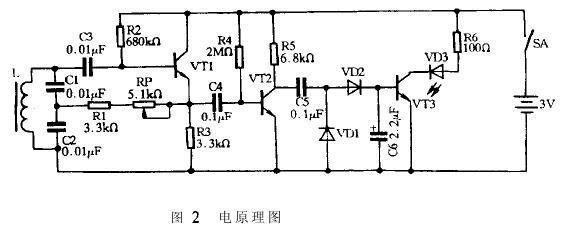
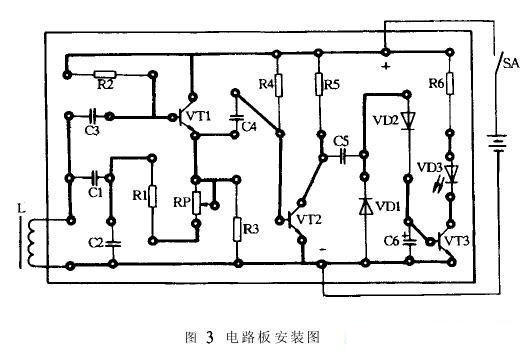
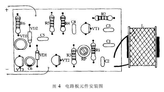
Figure 2 is the electrical schematic diagram of the metal detector, Figure 3 is its circuit board installation diagram, and Figure 4 is its circuit board component installation diagram. Before assembly, clean the pin leads of the components used and plate them with tin. Compare the three diagrams, solder the resistor, diode, capacitor, triode, light-emitting diode, and fine-tuning resistor to the circuit board in turn, and then connect the inductance probe, switch, and battery clip to the circuit board. After the circuit is installed and checked, it can be powered on for debugging. Turn on the power supply and slowly adjust the resistance of the fine-tuning resistor RP from large to small until the light-emitting diode lights up. Then use a metal object to approach the magnetic core end face of the inductance probe, and the light-emitting diode will go out. Adjusting the fine-tuning resistor RP can change the sensitivity of the metal detector. If the resistance of the fine-tuning resistor RP is too large or too small, the circuit will not work. If adjusted well, the detection distance of the circuit can reach 20mm. But be careful not to keep the inductance probe of the metal detector too close to the components, and do not use a metal shell when packing. If necessary, the inductance probe of the metal detector can also be led out and fixed with non-metallic materials.


3. Circuit Working Principle
The main part of the metal detector circuit is an oscillator in a critical state. When a metal object approaches the inductor L (i.e. the probe of the detector), the electromagnetic field generated in the coil will induce eddy current in the metal object. This energy loss comes from the oscillation circuit itself, which is equivalent to adding loss resistance to the circuit. If the metal object is close to the coil L, the loss in the circuit increases, the coil value decreases, and the oscillator, which is already in a critical state of oscillation, stops working. This controls the light-emitting diode behind it.
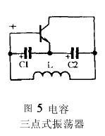
In this circuit, transistor VT1 and the peripheral inductor and capacitor form a capacitive three-point oscillator. Its AC equivalent circuit (ignoring the role of RP and R2) is shown in Figure 5. When there is a positive signal at the base of the transistor in Figure 5, the reverse action of the transistor makes its collector signal negative. The signal polarity at both ends of the two capacitors is shown in Figure 5. Through the feedback of the capacitor, the signal on the base of the transistor is in phase with the original one. Since this is positive feedback, the circuit can generate oscillation. The existence of RP and R1 weakens the positive feedback signal in the circuit, making the circuit just in the state of starting oscillation.

The oscillation frequency of the metal detector is about 40KHz, which is mainly determined by the inductor L, capacitors C1 and C2. Adjust the potentiometer RP to reduce the feedback signal so that the circuit is in a state of just starting. Resistor R2 is the base bias resistor of transistor VT1. The weak oscillation signal is sent to the voltage amplifier composed of transistor VT2, resistors R4, R5 and capacitor C5 through capacitor C4 and resistor for amplification. Then it is rectified by diodes VD1 and VD2 and filtered by capacitor C6. The rectified and filtered DC voltage turns on transistor VT3, its collector is at a low level, and the light-emitting diode VD3 is on.
When the inductance probe L of the metal detector approaches a metal object, the oscillation circuit stops oscillating, no signal passes through the capacitor C4, and the base of the transistor VT3 does not get a positive voltage, so the transistor VT3 is cut off and the light-emitting diode goes out.
- Detection of Bidirectional Trigger Diode
- 3 1/2, 4 1/2 digit intelligent digital voltmeter circuit composed of MAX1492/MAX1494
- Infrared detector
- Leakage Tester
- Transistor reverse breakdown voltage tester-----Transistor tester
- How to use STM32 to design an alcohol tester
- direct coupled amplifier circuit
- High current, high power amplifier circuit
- voltage amplifier circuit
- Phase sequence indicator circuit diagram
- Copier paper tail detection circuit composed of photoresistor sensor
- Three-phase AC power supply phase sequence detection circuit
- Transistor multiple "1" detection circuit
- Light detection circuit with current output
- and light detection circuit
- ADM690~ADM695 constitute a detection circuit (2)
- Hot spot sensor infrared detection circuit
- Human body detection circuit for infrared sensor
- Gas concentration detection circuit
- Combustible gas and toxic gas dual-purpose detection circuit


 京公网安备 11010802033920号