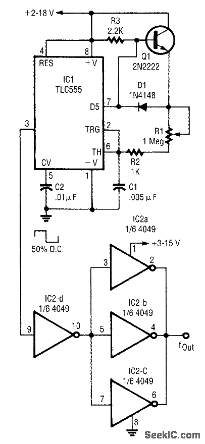
50% duty cycle 555 circuit
Source: InternetPublisher:newrudeman Updated: 2021/04/24

Uses external charging transistors and diodes to achieve 50% duty cycle and frequency control. When the 555 discharge transistor is switched off, the 2N2222 acts as a transmit follower. When the discharge transistor is on and 2N2222 is off, C1 is discharged through (R1+R2) at the same rate. The IN4l48 provides temperature compensation.
Latest 555 Circuits Circuits
- Variety of light-controlled electronic birds
- Four basic circuits of 555 monostable trigger
- 555 light control and infrared sensor energy-saving lamp circuit
- 555 four-digit display capacitance meter circuit
- 555 voice-activated duty alarm circuit
- 555 electronic flute circuit
- 555 three-state sound and light logic pen circuit
- 555 light intensity tester circuit
- 555 voice controlled lighting electronic wall clock circuit
- 555 electric bicycle pulse speed regulating device circuit
Popular Circuits
- NE555 time base integrated circuit diagram
- 50% duty cycle 555 circuit
- Self-stopping hypnotic device circuit diagram
- Double-key touch switch circuit diagram using 555 time base circuit
- Pulse width modulation circuit diagram based on 555 base time
- Electric bell sound delayer schematic diagram
- Integrated circuit timer 555 internal structure circuit diagram
- Circuit diagram based on 555 base time astable working mode
- 555 long learning time reminder circuit
- 555 Electronic disinfection circuit using ozone tube


 京公网安备 11010802033920号