How to Measure Turbidity of Liquids Using Arduino
Source: InternetPublisher:qoistoochee128 Keywords: Test measurement turbidity sensor Arduino Updated: 2024/12/19
Turbidity is an important term when it comes to liquids. As it plays an important role in liquid dynamics and is also used to measure water quality. So in this tutorial, let us discuss what is turbidity and how to measure the turbidity of a liquid using Arduino.
What is liquid turbidity?
Turbidity is the degree or level of cloudiness or turbidity of a liquid. This is due to the presence of a large number of invisible particles similar to white smoke in the air (with the naked eye). When light passes through a liquid, the light waves are scattered due to the presence of these tiny particles. The turbidity of a liquid is directly proportional to the free suspended particles, i.e. if the number of particles increases, the turbidity will also increase.

How to measure turbidity using Arduino?
As I mentioned earlier, turbidity occurs due to the scattering of light waves, and in order to measure turbidity, we should measure the scattering of light. Turbidity is usually measured in Nephelometric Turbidity Units (NTU) or Jackson Turbidity Units (JTLJ), depending on the method used for the measurement. Both units are roughly equivalent.
Now let's see how a turbidity sensor works, it has two parts, a transmitter and a receiver. The transmitter consists of a light source (usually an LED) and a driver circuit. On the receiving end, there is a light detector such as a photodiode or LDR. We place the solution between the transmitter and the receiver.
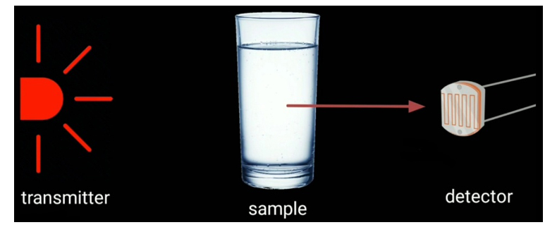
The transmitter simply transmits light, the light wave passes through the solution, and the receiver receives the light. Normally (no solution is present) the transmitted light is completely received on the receiver side. But in the presence of a turbid solution, the amount of transmitted light is very low. That is, at the receiving end, we only get low intensity light, and this intensity is inversely proportional to the turbidity. Therefore, we can measure turbidity by measuring the light intensity, if the light intensity is high, the solution is less turbid, if the light intensity is very low, it means that the solution is more turbid.
Components Needed to Make a Turbidimeter
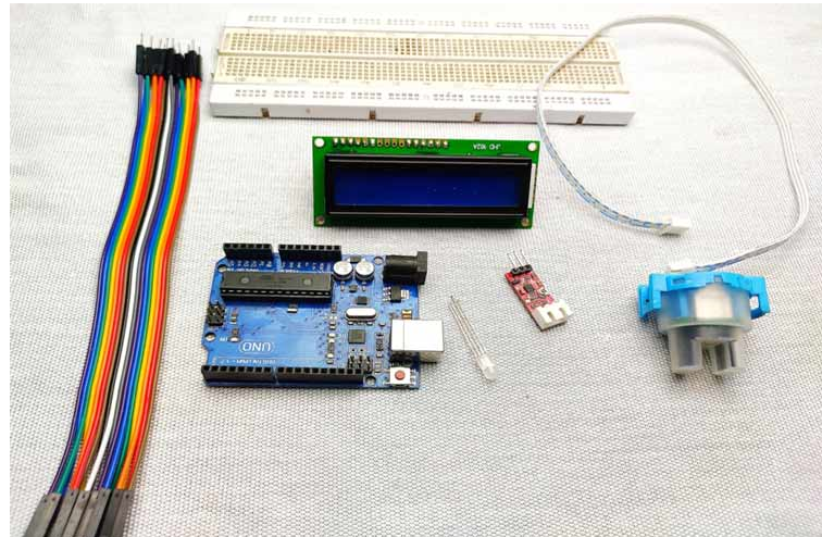
Turbidity Module
Arduino
16*2 I2C LCD screen
Common cathode RGB LED
Breadboard
Jumper Wires
Turbidity Sensor Overview
The turbidity sensor used in this project is shown in the image below.
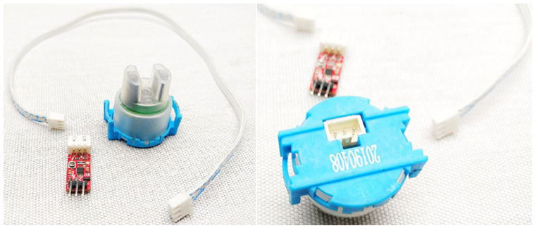
As you can see, this turbidity sensor module contains 3 parts. Waterproof lead wire, drive circuit, connecting wire. Test probe consists of transmitter and receiver.
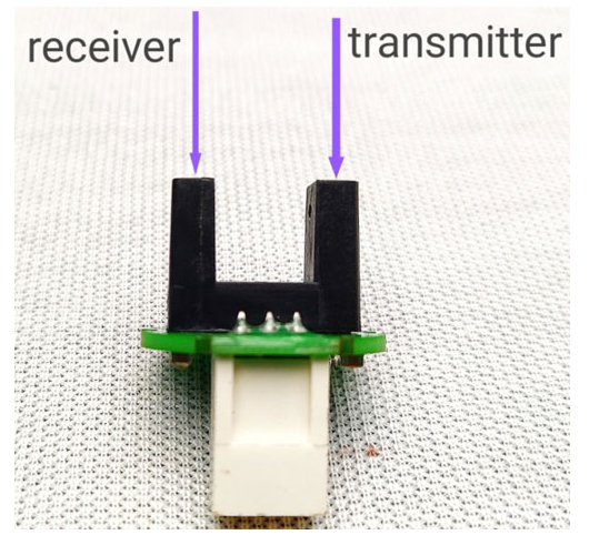
The diagram above shows that this module uses an IR diode as the light source and an IR receiver as the detector. But the working principle is the same as before. The driver section (shown below) consists of an op amp and some components that amplify the detected light signal.
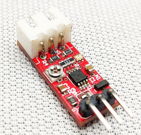
The actual sensor can be connected to this module using a JST XH connector. It has three pins, VCC, Ground and Output. Vcc is connected to 5v and ground. The output of this module is an analog value which varies according to the light intensity.
Main features of the turbidity module
Operating voltage: 5V DC.
Current: 30mA (max).
Operating temperature: -30°C to 80°C.
Compatible with Arduino, Raspberry Pi, AVR, PIC, etc.
Interfacing Turbidity Sensor with Arduino – Circuit Diagram
The complete schematic diagram for connecting the turbidity sensor to Arduino is shown below. The circuit was designed using Easy EDA.
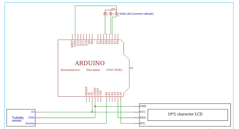
This is a very simple circuit diagram. The output of the turbidity sensor is analog, so it is connected to the A0 pin of the Arduino. The I2C LCD is connected to the I2C pins of the Arduino, i.e. SCL to A5 and SDA to A4. Then the RGB LED is connected to the digital pins D2, D3 and D4. After the connections are completed, my hardware setup is shown below.
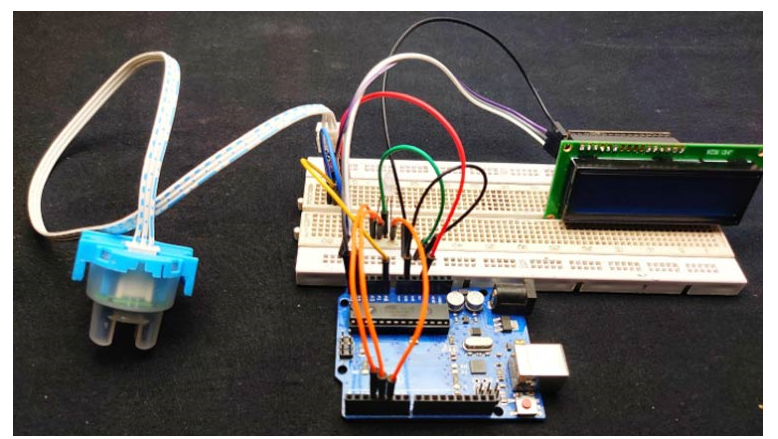
Connect the sensor's VCC to Arduino 5v, and then connect the ground to the ground. The sensor's output pin to Arduino's analog 0. Next, connect the LCD module's VCC and ground to Arduino's 5v and ground. Then SDA to A4, SCL to A5, these two pins are Arduino's I2C pins. Finally, connect the RGB LED's ground to Arduino's ground, and connect green to D3, blue to D4, and red to D5.
Programming Arduino to measure turbidity in water
The plan is to display the turbidity value from 0 to 100. That is, the meter should display 0 for pure liquid and 100 for highly turbid liquid. This Arduino code is also very simple and the complete code can be found at the bottom of this page.
First, I included the I2C Liquid Crystal library because we are using an I2C LCD to minimize the connections.
#include
Then I set the integers for the sensor inputs.
int sens
In the setup section I defined the pins.
pinMode(3, OUTPUT);
pinMode(4, OUTPUT);
pinMode(5, OUTPUT);
In the loop section, as I mentioned before, the output of the sensor is analog values. So we need to read these values. With the help of Arduino AnalogRead function, we can read the output values in the loop section.
int sensorValue =analogRead(sensorPin);
First, we need to understand the behavior of the sensor, which means we need to read the minimum and maximum value of the turbidity sensor. We can read this value on the serial monitor using the serial.println function.
To get these values, first, read the sensor freely without any solution. I get a value of about 640, then put a black mass between the transmitter and the receiver, we get a minimum value, which is usually zero. So we get a maximum value of 640 and a minimum value of 0. Now we need to convert these values to 0-100
For this purpose, I used the map function of Arduino.
int turbidity = map(sensorValue, 0,640, 100, 0);
Then I displayed these values on the LCD display.
lcd.setCu
After that, with the help of if condition, I gave different conditions.
if (turbidity < 20)
{
    digitalWrite(2, HIGH);
    digitalWrite(3, LOW);
    digitalWrite(4, LOW);
    lcd.setCursor(0, 1);
    lcd.print("It's cleared");
}
If the turbidity value is below 20 this will activate the green LED and display “its clear” on the LCD.
if ((turbidity > 20) && (turbidity < 50))
{
    digitalWrite(2, LOW);
    digitalWrite(3, HIGH);
    digitalWrite(4, LOW);
    lcd.setCursor(0, 1);
    lcd.print("It's cloudy");
  }
If the turbidity value is between 20 and 50, this will activate the blue LED and display "Turbid" on the LCD.
if ((turbidity > 50)
{
    digitalWri
If the turbidity value is greater than 50, this will activate the red LED and display “IT’S DIRTY” on the LCD as shown below.
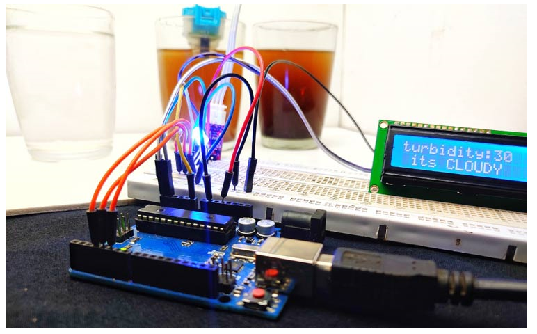
Just follow the circuit diagram and upload the code, if everything works correctly you should be able to measure the turbidity of the water and the LCD should display the quality of the water as shown in the picture above.
#include
- Lightweight and practical multi-core cable detection circuit
- Bat sound detection circuit
- Digital strain gauge circuit using MAX1492/MAX1494
- Inductive Pointer Watch Battery Tester
- How to Use a Radio as a Metal Detector
- A low-cost inductance meter consisting of a single IC
- AC ammeter circuit
- Directly coupled push-pull power amplifier circuit
- High-speed gain programmable amplifier circuit
- Numerical control following or inverting circuit
- LED lighting display detection circuit with overload protection
- Paper thickness detection circuit
- Overcurrent detection circuit
- Downhole oxygen concentration detection circuit
- Long-distance ringtone detection circuit using photoelectric coupler
- Using window discriminator as intensity detection circuit
- Transistor multiple "1" detection circuit
- Infrared two-dimensional temperature distribution detection circuit
- Revolution detection circuit
- Ferromagnetic material proximity detection circuit


 京公网安备 11010802033920号