|
802.11ax, also known as High-Efficiency Wireless (HEW), increases system capacity through a series of system features and multiple mechanisms, improves the working mode of Wi-Fi networks through better consistent coverage and reduced air interface medium congestion, and enables users to obtain the best experience; especially in dense user environments, it provides more users with consistent and reliable data throughput, with the goal of increasing the average user throughput by at least 4 times. In other words, Wi-Fi networks based on 802.11ax mean unprecedented high capacity and high efficiency.
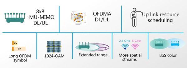
802.11ax Technology Structure
¡øSchematic diagram of 802.11ax technology modules
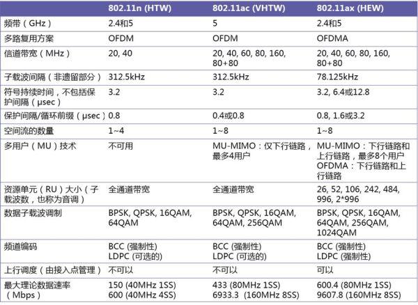
The 802.11ax standard introduces several significant changes in the physical layer. However, it is still backward compatible with 802.11a/b/g/n and ac devices. Because of this, 802.11ax STAs can transmit and receive data with legacy STAs, and legacy clients can demodulate and decode 802.11ax packet headers (although not the entire 802.11ax packet) and poll during 802.11ax STA transmissions. The following figure shows the most important changes in this standard revision and a comparison with the current 802.11n and 802.11ac.
¡ø Comparison of key PHYs of 802.11n, 802.11ac and 802.11ax
Analysis of key technologies
The following are the key technologies used in 802.11ax
OFDMA
MU-MIMO
1024-QAM
Spatial Reuse
¡¤ BBS Coloring
OFDMA (Orthogonal Frequency Division Multiple Access)
OFDMA is a method of adding multiple access in OFDM systems by assigning subsets of subcarriers to different users. So far, it has been adopted by many wireless technologies, such as 3GPP LTE. 802.11ax is the first WLAN standard to introduce OFDMA into WLAN networks. In addition, the 802.11ax standard also follows the LTE terminology and calls the smallest subchannel a "resource unit (RU)", with each RU containing at least 26 subcarriers.
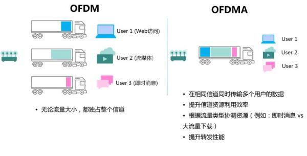
OFDMA allows multiple users with different bandwidth requirements to be served simultaneously, making efficient use of the available spectrum. The subcarriers are divided into several groups, each represented as a resource unit (RU) with a minimum size of 26 subcarriers (2MHz wide) and a maximum size of 996 subcarriers (77.8MHz wide). In OFDM used for traditional WLAN technology, the total channel bandwidth (e.g., 20MHz, 40MHz, etc....) is used for any one frame transmission. But in OFDMA used for 802.11ax, the subcarriers used can be allocated as small as 2 MHz blocks or as large as the maximum bandwidth transmission. Therefore, resources can be extended for different types of traffic, such as instant messaging (IM) versus video streaming. The difference between OFDM and OFDMA is shown in the figure below.
¡øComparison between OFDM and OFDMA
There are several subcarrier types:
Data subcarrier, used for data transmission;
Pilot subcarriers for phase information and parameter tracking;
Unused subcarriers are not used for data/pilot transmission. Unused subcarriers are DC subcarriers.
¡¤ Guard band subcarriers, at the edge of the band;
¡¤ Null subcarriers.
The subcarriers forming the RU are contiguous, except in the middle of the band where a null is placed at DC.
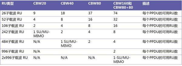
The OFDMA structure consists of 26 subcarrier RU, 52 subcarrier RU, 106 subcarrier RU, 242 subcarrier RU, 484 subcarrier RU and 996 subcarrier RU. The maximum number of RUs is shown in the figure below, and the RU position depends on the channel bandwidth.
¡øTotal number of RUs of different bandwidths
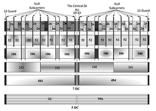
The following figure shows the RU locations of 26, 52, 106, 242, 484 and 996 subcarriers for 80MHz channel bandwidth. A user can only be assigned to one RU, and RU size ¡Ý 106 can be assigned to multiple users.
¡øSchematic diagram of RU position in 80MHz
MU-MIMO (Multi-User Multiple Input Multiple Output)
I believe everyone is familiar with MU-MIMO. When 802.11ac was introduced, DL MU-MIMO was introduced, but the following problems were encountered:
Many client devices are single-antenna, and many two-antenna clients switch to single-stream mode for DL MU-MIMO to prevent interference:
With a 4-antenna AP, the gain compared to a single user is modest;
Even if an 8-antenna AP is built, the grouping is limited to 4 users;
Channel probe responses from users are sent continuously in time, resulting in high overhead;
TCP/IP with TCP ACK on uplink is impaired without UL MU enhancement;
UL MU-MIMO was originally considered in 11ac but was not included due to implementation issues.
The enhancements of 802.11ax MU-MIMO are as follows:
Support for UL MU-MIMO:
Probe frames, data frames, etc. can be grouped among multiple users to reduce overhead and increase uplink response time;
For DL and UL, expansion to eight users:
MU-MIMO throughput can now be doubled or tripled in single-user operation, even when the device is in single-stream mode.
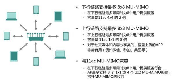
The 802.11ac standard introduced 4x4 downlink MU-MIMO, where the AP sends independent data streams to up to four STAs simultaneously. 802.11ax expands the maximum number of users supported by downlink MU-MIMO to 8. It also adds support for 8x8 uplink MU-MIMO, allowing up to 8 STAs to transmit simultaneously to a single AP over the same frequency resources. The result is a 2x increase in downlink capacity and an 8x increase in uplink capacity compared to 802.11ac.
¡øFeatures of 802.11ax MU-MIMO
MU MIMO and OFDMA technologies can be used simultaneously. To enable uplink MU transmission, the AP sends a new control frame called a trigger frame, which contains RU allocation scheduling information for STAs, the coding type and modulation and coding scheme (MCS) for each STA in the triggered PPDU. In addition, the trigger frame provides synchronization for uplink transmission.
Since multiple transmitters participate in UL MU-MIMO transmission, it requires time, frequency, sampling clock, and power pre-correction of participating STAs to alleviate synchronization-related issues at the AP.
Multi-user on-chain operation
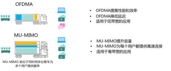
In 802.11ax, MU-MIMO and OFDMA technologies can be used separately. In multi-user operation mode, the standard specifies two ways to perform multitasking operations for more users in a specific area depending on the situation: multi-user multiple input and multiple output (MU-MIMO) or orthogonal frequency division multiple access (OFDMA). In either case, the wireless access point will act as a central controller for multi-user operations, which is similar to the way LTE base stations are used to control multi-user multitasking.
¡ø Use OFDMA and MU-MIMO depending on the type of application being served
By understanding their working mechanisms, you can see that OFDMA increases air interface efficiency, which greatly reduces application latency. It is more efficient and effective in transmitting small data packets within the range of the workable signal-to-noise ratio, and is extremely suitable for wireless voice or similar application scenarios. MU-MIMO improves system capacity and is more efficient in transmitting large data packets under high signal-to-noise ratio conditions, making it suitable for video, web browsing, and office scenarios and applications.
Of course, 802.11ax access points can also combine MU-MIMO and OFDMA operations. To coordinate uplink MU-MIMO or uplink OFDMA transmissions, the access point sends a triggered management frame to all users. The management frame indicates the number of spatial streams and/or OFDMA configuration (frequency and RU size) for each user. In addition, it also contains power control information so that individual users can increase or decrease their transmission power, thereby balancing the power received by the wireless access point from all uplink users and improving frame reception at more distant nodes. The wireless access point also indicates when all users can start and end transmission. As shown in the figure below, the wireless access point sends a multi-user uplink triggered management frame to tell all users when they can start transmitting together and the duration of the frame to ensure that they can end their transmission at the same time. Once the wireless access point has received the frames from all users, it will send back a Block ACK to end the operation.
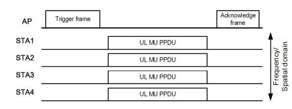 ¡øBasic frame exchange sequence for UL MU transmission
In a competitive environment, users do not have to compete with each other to send data in the uplink, but the 802.11ax wireless access points coordinate to avoid conflicts with each other. This management method will achieve better resource utilization and efficiency.
1024-QAM
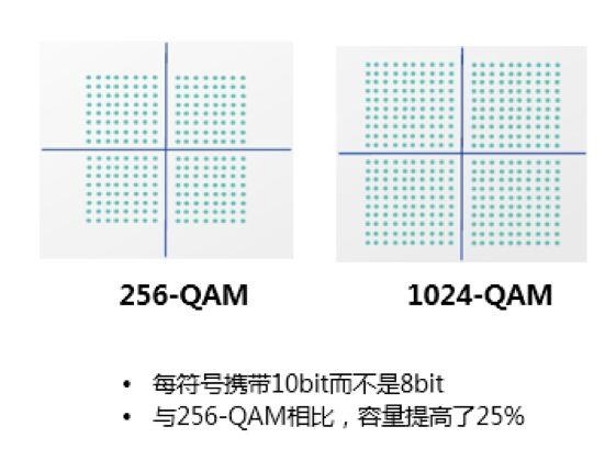
QAM coding uses constellation diagrams (dot diagrams) to modulate and demodulate data. In practical applications, it is a relationship of 2 to the power of N. For example, 16-QAM, 16 is 2 to the power of 4, and 4 bits of data can be transmitted at a time; 802.11n is 64-QAM, which is 2 to the power of 6. Therefore, in a constellation set of 64 dots, any point can carry six bits of data information.
In 802.11ac, it becomes 256-QAM, which is 2 to the 8th power. The coding rate of 802.11ac is 33% higher than that of 802.11n. 802.11ax introduces a higher-order coding, which is 2 to the 10th power, 1024-QAM.
We all know that the improvement from 8 to 10 is 25%, which means that compared with 802.11ac, the performance of 802.11ax has been improved by 25%, becoming 1024-QAM, and one symbol can carry 10 bits of data.
¡øComparison between 256-QAM and 1024-QAM
Spatial Reuse
To improve system-level performance and efficient use of spectrum resources in dense deployment scenarios, the 802.11ax standard implements spatial reuse technology. STAs can identify signals from overlapping basic service sets (BSSs) and make decisions about medium contention and interference management based on this information.
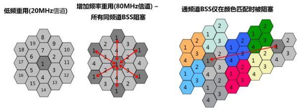
When a STA actively listening to the medium detects an 802.11ax frame, it checks the BSS color bit or MAC address in the MAC header. However, with existing medium access rules, devices from one BSS will defer to another co-channel BSS without increasing network capacity.
BSS coloring, a mechanism introduced in 802.11ah to assign a different ¡°color¡± to each BSS, is extended to 11ax to assign new channel access behaviors based on the detected color.
¡øBSS coloring mechanism
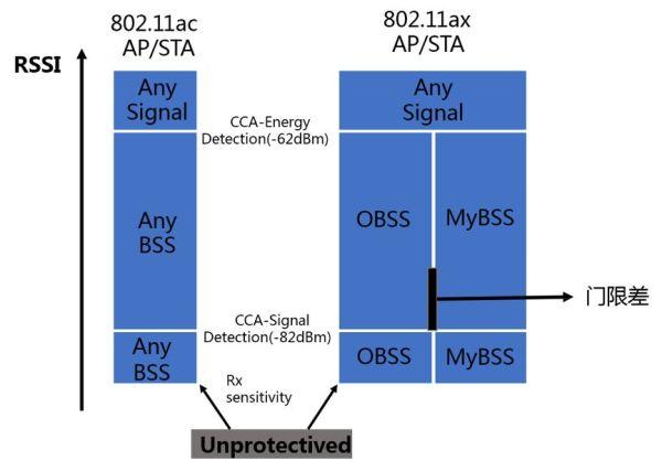
When 802.11ax STAs use color code-based CCA rules, they can also adjust the OBSS signal detection threshold together with transmit power control. This adjustment can improve system-level performance and use of spectrum resources. In addition, 802.11ax STAs can adjust CCA parameters such as energy detection level and signal detection level.
¡øDynamically adjust the CCA threshold within the BSS
In addition to using CCA to determine whether the medium is idle or busy for the current frame, the 802.11 standard also uses the Network Allocation Vector (NAV), a timer mechanism that maintains a prediction of future traffic so that STAs indicate the time of the frame they need immediately following the current frame. NAV acts as a virtual carrier sense, ensuring medium reservation for frames critical to 802.11 protocol operation, such as control frames, and data and ACK after RTS/CTS exchanges.
Intra-BSS NAV: If the BSS color in the detected protocol data unit (PPDU) is the same as the color announced by the associated AP, the STA will treat the frame as an Intra-BSS frame;
¡¤ Inter-BSS NAV: If the BSS color of the detected frame is different, the STA will regard the frame as an Inter-BSS frame from the overlapping BSS. After that, the STA will regard the medium as BUSY only when the STA needs to verify whether the frame is an Inter-BSS frame.
The standard must still define some mechanism for ignoring traffic from overlapping BSSs, but the implementation could include raising the Clear Channel Assessment Signal Detection (SD) threshold for inter-BSS frames while keeping the threshold lower for intra-BSS traffic. This way, traffic from neighboring BSSs does not create unnecessary contention for channel access.
Summarize
Generally speaking, 802.11ax has achieved its set goals in two major aspects, among which MU-MIMO and OFDMA are the key to the success of 802.11ax.
1. Enhancement and efficiency of the physical layer, mainly including:
¡¤ Orthogonal Frequency Division Multiple Access (OFDMA) in both uplink and downlink directions The OFDMA mechanism can provide smaller (but dedicated) sub-channels to multiple users simultaneously, thereby improving the average transmission rate for each user.
Multi-User Multiple Input Multiple Output (MU-MIMO) in both uplink and downlink directions: The uplink can serve up to eight users simultaneously, eight times the capacity of 802.11ac; the downlink can serve up to eight users simultaneously, twice the capacity of 802.11ac.
In 802.11ax, MU-MIMO and OFDMA technologies can be used separately; OFDMA increases air interface efficiency, while MU-MIMO improves system capacity.
Up to 8 transmit antennas, 8 receive antennas, and 8 spatial streams
Higher modulation method, 1024-QAM can carry 10 bits per symbol, which increases the capacity by 25% compared with 256-QAM.
2. Enhancement and efficiency of the MAC layer, mainly including:
Basic Service Set Coloring (BSS Coloring) The BSS Coloring mechanism enables a device to distinguish transmissions in its own network from those in neighboring networks, minimizing co-channel interference as much as possible.
Dual NAV mechanism with both Intra-BSS NAV and Inter-BSS NAV can help STAs predict the traffic within their own BSS, and they can transmit freely when they know the overlapping traffic status
Target Wake up Time (TWT) reduces contention and overlap between users and significantly increases STA sleep time to reduce power consumption
Ruijie Networks has released a new product based on the 802.11ax platform, the RG-AP860-I, which uses a higher-order 1024-QAM modulation and coding scheme and uplink and downlink OFDMA technology. With higher transmission rates, stronger concurrency capabilities, and more efficient resource scheduling capabilities, it demonstrates the shocking power of a single AP carrying a 10Gbps network access rate. The most critical point is that Ruijie RG-AP860-I fully supports 802.11ax enterprise-level applications, which has opened up the road to large-scale commercial applications for the seventh-generation wireless technology.
| 


 ÌáÉý¿¨
 ±äÉ«¿¨
 ǧ½ï¶¥
ǧ½ï¶¥