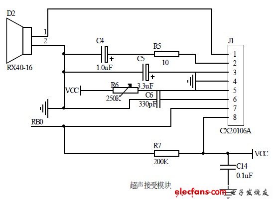
The ultrasonic receiving circuit diagram is shown below:
When ultrasonic waves propagate in the air, their energy will continue to attenuate as the distance increases. Through experimental measurements, when the detection distance is about 1m, the signal energy has attenuated to about 30mv. We need to amplify and filter the received weak ultrasonic sinusoidal signal and input it to the external interrupt port of the PIC as a sign of receiving the echo. The usual design idea is to first use an LM series amplifier for amplification, and then input it to INT0 to generate an interrupt through filtering, frequency locking and other circuits. The advantage of this method is that it can lock the required frequency to prevent interference from other frequencies of ultrasonic waves from the outside, but the disadvantage is that the integration is not high, and the design and welding are cumbersome. For this purpose, this paper adopts Sony's CX20106A infrared remote control receiver integrated chip, which can be used for ultrasonic processing circuits. It integrates functions such as amplification, limiting, bandpass filtering, peak detection, shaping and comparison, and has high sensitivity and anti-interference [5]. Pin 7 of the CX20106A chip is connected to the INT0 of the PIC microcontroller. When no ultrasonic wave is received, pin 7 outputs a high level of about 4.1V and no interruption occurs; when an ultrasonic wave that matches or is close to the center frequency of 40KHz is received, a low jump occurs.
When a bottom transition is detected, the first falling edge signal is input to INT0 as an external interrupt signal, then timer T1 is turned off and the count value of T1 is read to perform the next step of time and distance calculation.

Figure 1. System transmitting circuit diagram.
Previous article:Ultrasonic distance measurement alarm system peripheral circuit diagram
Next article:Ultrasonic transmitter circuit diagram
- Popular Resources
- Popular amplifiers
- USB Type-C® and USB Power Delivery: Designed for extended power range and battery-powered systems
- ROHM develops the second generation of MUS-IC™ series audio DAC chips suitable for high-resolution audio playback
- ADALM2000 Experiment: Transformer-Coupled Amplifier
- High signal-to-noise ratio MEMS microphone drives artificial intelligence interaction
- Advantages of using a differential-to-single-ended RF amplifier in a transmit signal chain design
- ON Semiconductor CEO Appears at Munich Electronica Show and Launches Treo Platform
- ON Semiconductor Launches Industry-Leading Analog and Mixed-Signal Platform
- Analog Devices ADAQ7767-1 μModule DAQ Solution for Rapid Development of Precision Data Acquisition Systems Now Available at Mouser
- Domestic high-precision, high-speed ADC chips are on the rise
- Intel promotes AI with multi-dimensional efforts in technology, application, and ecology
- ChinaJoy Qualcomm Snapdragon Theme Pavilion takes you to experience the new changes in digital entertainment in the 5G era
- Infineon's latest generation IGBT technology platform enables precise control of speed and position
- Two test methods for LED lighting life
- Don't Let Lightning Induced Surges Scare You
- Application of brushless motor controller ML4425/4426
- Easy identification of LED power supply quality
- World's first integrated photovoltaic solar system completed in Israel
- Sliding window mean filter for avr microcontroller AD conversion
- What does call mean in the detailed explanation of ABB robot programming instructions?
- STMicroelectronics discloses its 2027-2028 financial model and path to achieve its 2030 goals
- 2024 China Automotive Charging and Battery Swapping Ecosystem Conference held in Taiyuan
- State-owned enterprises team up to invest in solid-state battery giant
- The evolution of electronic and electrical architecture is accelerating
- The first! National Automotive Chip Quality Inspection Center established
- BYD releases self-developed automotive chip using 4nm process, with a running score of up to 1.15 million
- GEODNET launches GEO-PULSE, a car GPS navigation device
- Should Chinese car companies develop their own high-computing chips?
- Infineon and Siemens combine embedded automotive software platform with microcontrollers to provide the necessary functions for next-generation SDVs
- Continental launches invisible biometric sensor display to monitor passengers' vital signs
- (Reprinted) Introduction to nRF5 chip peripherals GPIO and GPIOTE
- Switching power supply output efficiency problem
- Recommend a mall for purchasing electronic components: free shipping for new customers’ first order, and also provide services such as sample application and technical support!
- Membrane switch components
- Zhengzhou Customs destroyed 20,000 counterfeit Texas Instruments integrated circuits. Have you ever come into contact with counterfeit and shoddy products at work?
- PWM input capture, problem of selecting trigger source
- Prize-giving event | Watch the short video "Keysight Automotive Ethernet and Radar Testing" and get a gift
- MSP430FR5969BOOT Programming and Application Programming
- 4.2V to 50V
- Qorvo CEO Bob Bruggeworth Elected Chairman of the Semiconductor Industry Association

 Research on Ultrasonic Collision Avoidance Warning System


 京公网安备 11010802033920号