Traditional water supply metering operations are usually carried out by sending people from various management departments to the meter installation site to read the meter. Due to the wide range of users and large volume, it is very easy to make mistakes. Manual meter reading is not only inefficient, but also not conducive to scientific management, which brings great difficulties to the modeling, analysis, and planning of urban pipe networks. The rapid development of electronic and computer technology has provided a large environment for the realization of automatic meter reading technology, and the modernization of the management system also calls for the arrival of the era of automatic meter reading. At present, China generally adopts the method of installing water meters indoors in users and charging for meter reading at home every month. This brings a lot of trouble to users and troubles to meter readers, causing many unnecessary disputes. In order to effectively solve the many drawbacks of meter reading charges at home, improve efficiency, avoid public security problems caused by meter reading at home (such as impersonating to charge and robbing) and eliminate arrears of fees, the call for outdoor metering of water meters is getting louder and louder. Especially for high-rise and millennial residential areas, outdoor metering of water meters is very necessary. The traditional meter reading method can no longer meet the development requirements of future residences.
With the development of electronic technology, sensor technology, automatic control technology and computer technology, many products for outdoor metering of water meters have been developed. There are mainly three outdoor metering methods: IC card, power carrier, and remote meter reading. The Ministry of Construction's "2000 Well-off Urban and Rural Housing Science and Technology Industry Project Urban Demonstration Community Planning and Design Guidelines (Revised Draft)" has clearly stated: "Promote the application of outdoor metering (including water, electricity, heating, and gas meters) technology." It is also clearly stated in the "Outline of China's Residential Product Development" that "convenient metering without disturbing residents, so that a large amount of manual metering work will gradually transition to digital transmission, and develop intelligent water, electricity, gas, and heat metering devices and interface boxes." At present, the intelligent meter reading system for outdoor water metering has met the requirements for use. Therefore, combining sensor technology and radio frequency technology, and using the existing widely used telephone network, a unique structure, stable performance, and completely reliable tap water intelligent meter reading system has been designed and developed.

1 Design requirements
In order to ensure the accuracy and reliability of the tap water intelligent meter reading system and improve the scientificity and standardization of energy management, the following requirements are put forward for the intelligent meter reading system:
(1) The water meter is a sealed structure and is a new type of meter that can not only intuitively display relevant energy consumption metering data but also generate energy consumption metering pulse signals.
(2) The system has a power failure prevention function. In the event of a power failure, the transmitter and the receiver are equipped with backup batteries to prevent data loss.
(3) The system uses a high-precision real-time clock that does not lose power to provide a reliable time reference for data time-sharing processing; it can realize the time-sharing billing function; and it can alarm and record the time of fault occurrence through communication equipment failure.
(4) Database security. The database is read-only and only authorized administrators can write data. The management center computer has a password to prevent unauthorized personnel from operating. The password can be modified by the operator on the host. It can provide billing query, report generation, printing, alarm and other functions.
2 Overall structure
There are two forms of intelligent meter reading systems:
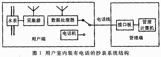
(1) The user's room is equipped with a telephone. The structure of the meter reading system is shown in Figure 1. Data acquisition transmits data to the data processor via wireless communication, and the data processor reports data to the management computer via telephone lines.
(2) If there is no telephone in the user's room, the meter reading system structure is shown in Figure 2. The data collector transmits data to the data processor via wireless communication. The data processor is installed in the outdoor corridor and is equipped with a display module to display the user's current water consumption. The data processor installed in the corridor reports data to the management computer via public telephone lines. If the resident's room is shielded by iron doors and wireless communication cannot be achieved, a dedicated communication line can be laid to upload the data.

3 System composition
(1) Water meter. The metering water meter used in this system is a new type of metering instrument that can not only visually display relevant energy consumption metering data, but also generate energy consumption metering pulse signals. It is actually a water meter equipped with a permanent magnet and a Hall element to form a magnetoelectric sensor. The Hall element is fixedly installed near the counting turntable, and the permanent magnet is installed on the counting disk (for example, 0.1m3 or 0.01m3). When the turntable rotates once, the permanent magnet passes through the Hall element once, that is, a metering pulse is generated at the signal end, corresponding to 0.1m3 or 0.01m3, which is sent to the data processor via a wireless transmitter. In addition, an anti-theft Hall element is also installed on the water meter. When a user steals water, the Hall element sends an alarm signal to the data processor, and the data processor then reports it to the management computer through the telephone line for processing.
(2) Data processor. The data processor is a multi-functional module that realizes the automatic reading and collection of water meter data, stores the data for a long time and reliably, and transmits it to the management computer when needed. Specifically, it is used to receive water meter data and various alarm signals, accumulate household water consumption, and regularly send relevant data of residents to the management computer through telephone lines. One data processor corresponds to one water meter and is generally installed near the telephone. The data processor has a rechargeable current as a backup power supply. In the event of a power outage, the charging current will be used to supply power to the data processor alone to ensure the normal operation of the data processor.
(3) Management computer. The management computer is the management core of this system. It can connect many data processors through telephone lines. The number of data processors is basically unlimited. The management computer can read the data of each user's water meter at any time and save the data in the database for query. It can manage the entire system and process the read data.

[page]
4 System Hardware Electrical Principles
4.1 Electrical Principles of Water Meter Transmitter
The function of the water meter transmitter is to transmit the water consumption measured by the water meter to the data processor by wireless communication. The block diagram is shown in Figure 3. The Hall sensor installed in the water meter is used to detect the water consumption. For every 0.1t of water flowing through the water meter, the Hall sensor sends a pulse signal, which generates a red 1s wide pulse through the series steady-state circuit, and then is shaped by the Schmidt inverter 4069 and sent to the encoder PT2262 for encoding. The PT2262 full code address is 4 11. The encoded data is sent to the wireless transmission module for transmission. The radio transmission frequency is 400MHz and the effective distance is 50m. At the same time, the transmitter also has some additional functions.
(1) Anti-theft function. Due to the characteristics of dry water meters relying on electromagnetic transmission, they are easily affected by external magnetic fields. If the user places a strong magnet near the water meter, it will reduce the speed of the water meter transmission gear and reduce the measurement accuracy of the water meter. The transmitter is also equipped with a Hall sensor dedicated to measuring magnetic field strength. When a strong magnetic field is detected near the water meter, the Hall sensor sends an alarm pulse, which is wirelessly transmitted to the data processor through the transmitter.
(2) Backup battery. To ensure that the transmitter can work normally during a power outage, while the AC 220V power supply is provided, there is also a 4.8V nickel-hydrogen battery and a battery voltage monitoring and charging circuit composed of LM358 and 555 to enable the battery to be charged normally. The backup battery can maintain the transmitter's continuous operation for 48 hours.
4.2 Principle of the electrical part of the data processor
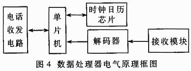
The data processor is the key equipment of this system. It consists of a wireless receiving and decoding part, a clock calendar, 8051 and peripherals, a telephone transceiver circuit, a power supply, etc. The block diagram is shown in Figure 4. The wireless receiving module and the transmitting module work at the same frequency of 400MHz; decoding is completed by PT2272, the working frequency is the same as PT2262, and the address code is consistent with PT2262. The clock calendar chip DALLAS12887 provides the system with an accurate 100-year clock calendar, including year, month, day, hour, minute, second, week and timing alarm signal.

The telephone receiving and transmitting routing dialing circuit and audio decoding circuit are composed. The 4-16 decoding wife MC4514 analog switch 4066 forms a 3*4 virtual keyboard array. The 8051 controls the opening and closing of the keys to complete the encoding of the telephone number to be dialed and the uploaded data, and sends the telephone number and data to the dialing circuit. The dial-up dedicated chip is W91312, and the crystal frequency is 3.58MH. After receiving the telephone number from the management computer, it will be dialed immediately. When the handshake signals at both ends are completed and the line is confirmed to be connected, the 8051 controls the uploaded data to be output to the management computer in audio mode; the function of the audio decoding circuit is to decode the audio signal and output it in the form of BCD code. When the data processor dials the management computer, the management computer replies with a connection handshake signal. The signal is an audio signal. After being amplified by the AC amplifier circuit, it is sent to the audio decoding chip MC145436 for decoding, and finally sent to 8051 in the form of BCD code.
The system is powered by 220V AC and lithium backup battery. When the residential power outage or artificial power outage occurs, the system can still maintain normal operation for 48 hours.
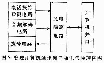
4.3 Principle of the electrical part of the management computer communication interface board The
management computer communication interface board consists of a dialing circuit, an audio decoding circuit, a telephone ringing detection circuit, a photoelectric isolation circuit and a power supply circuit, as shown in Figure 5. The dialing circuit and audio decoding circuit are the same as those on the digital processor board.

5 System software
This system software consists of three parts: data receiving, data conversion and charging system.
(1) Data receiving system. Since it is necessary to read the user's water consumption from the parallel port, the data receiving system will convert the user's data into a text file after the user's water consumption is up. This system starts automatically after the operating system starts and is always in working condition.
(2) Data conversion system. Considering that the data after receiving is a text file and cannot be directly entered into the database, a data conversion system is designed to store the data into the database. This system starts automatically after the operating system starts and is always in working condition.
(3) Charging system. After the legitimate user logs in to this system, daily business processing is carried out. According to the user's computer configuration, the system can run in a stand-alone environment or in a network environment.
The requirements for computer software and hardware in the stand-alone operating environment are: the operating system is WIN95/WIN98; the database is Oracle734.
The network operating environment has the following requirements for computer software and hardware: the client of the operating system is WIN95/WIN98, and the server is WIN2000/WINNT;
the client of the database is Oracle734; the server is Oracle8i;
the hard disk is 5G;
water, as a limited resource, is increasingly valued by people. Saving water is no longer an initiative, but our responsibility and obligation. Therefore, it is very urgent to accurately measure the water used by residents, enterprises and institutions. One valve per household and one meter per household are the general trend. On the other hand, with the implementation of the one-household-one-meter project, the difficulty of measuring and charging for residents' water use has gradually increased. In order to effectively solve the many drawbacks of household meter reading, improve efficiency, avoid public security problems caused by household meter reading, and prevent arrears of fees. Therefore, it is imperative to replace traditional household meter reading with outdoor intelligent meter reading.
Among the existing intelligent meter reading systems, some are realized through power line carrier network, and some are realized through laying dedicated lines. Comparing the two intelligent meter reading systems, the power line carrier network has relatively large limitations, mainly due to the limitation of transformers; the construction project is relatively large and the transformation cost is relatively high when the dedicated line is laid. Therefore, the use of the public telephone network to realize the intelligent meter reading system avoids the above-mentioned unfavorable factors, has a wide range of applications, is easy to install, does not require laying lines, and has relatively low transformation costs, which brings a lot of convenience to users. Therefore, the application prospects are very broad.


 Mission-oriented wireless communications for cooperative sensing in intelligent unmanned systems


 京公网安备 11010802033920号