Author : Zhen Zhu
In China, there is a requirement for full voltage loss detection for three-phase electricity meters. This requirement defines a full voltage loss condition as when the input voltage is all below the threshold and the current is greater than 5% of the rated current.
When a full voltage loss event occurs, the meter records the phase voltage, phase current, power factor, and active power. The meter is designed with dual power supplies. The primary power supply is based on the external power line voltage input, and the backup power supply is based on an external battery. When a full voltage loss event occurs, the AC/DC power supply stops working, and the battery-powered microcontroller sets the ADE9078 analog front end (AFE) to detect current.
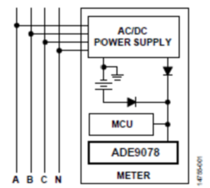
Figure 1. Block diagram of the power supply circuit for an energy meter. This application note describes how to configure the ADE9078
to detect a total voltage loss event.
This section describes the power modes of the ADE9078. The ADE9078 has four power modes to switch between. Users can select different power modes to save power.
Table 1 shows the technical specifications of the different power modes.

Table 1. Power Consumption in Various Power ModesPower
Saving Mode 0 (PSM0) is a fully functional mode that consumes 12 mA. The user can set the PSM0 mode to read/write all registers in the ADE9078. PSM0 is suitable for the power line powered mode. Normally, the ADE9078 operates in PSM0 mode, which means that at least one phase of the voltage is powering the meter.
PSM1, PSM2, and PSM3 support low power tamper detection, which is required in China. Using these operating modes, the user can detect whether there is power tampering. In situations involving power tampering, batteries are usually used to power the ADE9078. The
tamper measurement mode PSM1 allows the user to quickly measure key parameters such as current rms (IRMS), voltage rms (VRMS), power, and reactive volt-amperes (VAR) with lower power consumption than PSM0. It uses a different calculation method than PSM0. These measurements are calculated in 20 ms. In IRMS measurement, PSM1 mode detection takes 40.5 ms with a dynamic range of 600:1 and achieves an accuracy of less than 0.2%. For power, PSM1 mode takes 40.5 ms with a dynamic range of 600:1 and achieves an accuracy of less than 0.2%.
In PSM2 mode of operation, the ADE9078 enters a low power state with only the internal low power comparator active. The low dropout regulator (LDO), analog-to-digital converter (ADC), digital signal processor (DSP), and crystal oscillator are all powered down. The input currents IA, IB, and IC are compared to the user selected levels set in the PSM2_CFG register and an interrupt is generated and the pin is triggered if any current exceeds the threshold  . The time taken to detect the peak current is determined by the user and is set in the LPLINE[4:0] bits of the PSM2_CFG register. The measurement cycle time is (LPLINE[4:0] + 4)/50 seconds. When the signal on a current channel is greater than the peak value for more than LPLINE[4:0] + 1 times, the ADE9078 indicates that a tampering condition has been detected. The maximum allowed value of LPLINE[4:0] is 0x0A.
PSM3 is an idle mode, which means that all functions inside the ADE9078 are shut down and the current consumed is less than 1 µA.
The PM0 and PM1 pins (PMx) control the PSMx mode, where x refers to PSM0 to PSM3.
Table 2 shows the PMx states and the associated PSMx modes.
Table 2. PMx States and Associated PMx Modes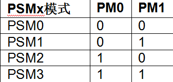
Use the MCU's input/output pins to connect the PM0 and PM1 pins to select the power mode.
Hardware Solution
As shown in Figure 2, there are two power supplies in the meter: the AC/DC converter and the battery. They are switched by two diodes. The MCU detects the voltage output of the AC/DC power supply. If there is no voltage output, all phases (A, B, and C) are powered off. In this case, the MCU starts the full voltage loss detection function. When one of the phases is powered on, the AC/DC power supply outputs voltage to power the meter. Otherwise, the AC/DC is turned off, and the input/output pin triggers a low voltage to notify the MCU that a full voltage loss condition has occurred and the battery is supplying power. In this case, the MCU and ADE9078 enter low power mode.
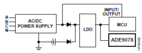
Figure 2. Power Switching Circuit Block Diagram
Figure 3 shows the wiring requirements for the full voltage loss detection function between the MCU and the ADE9078. If a full voltage loss event occurs, the MCU will put the ADE9078 into a low power mode through the PM0 and PM1 pins.
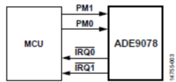
Figure 3. Hardware wiring and software program between MCU and ADE9078 for full voltage loss detection function
Figure 4 shows the steps for total voltage loss detection.
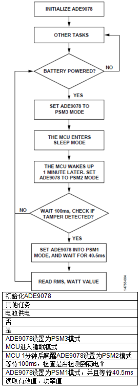
Figure 4. Software routine for no voltage detection
PSM2_CFG is the configuration register for PSM2 mode and is set during the initialization of the ADE9078. For example, if the rated current is 10 A, the current transformer ratio is 2500:1, and the load resistance is 12.5 Ω, then at 5% of the rated current, the dynamic ratio of the peak value is: The 
PKDET_LVL bits (Register 0x4B8, Bits [8:5]) are used to configure the low power comparator peak current detection level.
Table 3 shows the meaning of the settings.
Table 3. PSM2 Current Peak Detection Thresholds
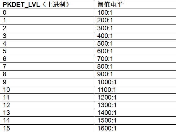
When PSM2_CFG[8:5] is set to 3, it means the threshold level is 400:1.
LPLINE[4:0] is set to 1, so the measurement period of PSM2 mode is (1 + 4)/50 = 100 ms.
When initializing the ADE9078, set the PSM2_CFG register (Register 0x4B8) to 0x31.
Power Calculation
When power tampering is detected, the ADE9078 consumes the maximum current. The MCU sets the ADE9078 to PSM1 mode to read the effective value and power value for event recording. The power consumption of the ADE9078 in each link is as follows:
•PSM3 mode: 60 s × 2 μA = 120 μA
•PSM2 mode: 100 ms × 200 μA = 20 μA
•PSM1 mode: 40.5 ms × 9 mA = 364.5 μA
The total power consumption is: 120 + 20 + 364.5 = 504.5 μA. If power tampering continues for 7 days, the power consumption will be: 
When power tampering is not detected, the ADE9078 consumes the minimum current. The ADE9078 does not enter PSM1 mode because there is no need to record effective values. The power consumption of the ADE9078 in each phase is as follows:
• PSM3 mode: 60 s × 2 μA = 120 μA
• PSM2 mode: 100 ms × 200 μA = 20 μA
The total power consumption is 120 + 20 = 140 μA. If this situation continues for 7 days, the power consumption will be:
The current mainstream external battery capacity is 1.2 Ah; therefore , even if power theft occurs, it is easy to meet the power consumption requirements of the ADE9078.
In both PSM2 and PSM3 modes, AVDDOUT and DVDDOUT are powered down. When entering PSM1 mode from PSM2 or PSM3 mode, AVDDOUT and DVDDOUT are powered up. Figure 5 shows the actual measurement results on the ADE9078 reference meter.
Figure 5. Power-up sequence for entering PSM1 mode
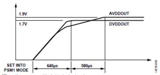
When the PM1 pin is set low, the PM0 pin is set high, and both pins reach a regulated voltage, AVDDOUT and DVDDOUT start to rise from 0 V, and the ADE9078 enters PSM1 mode.
1. Another test measures the time consumed by tamper detection in PSM2 mode. LPLINE[4:0] is set to 1. Ideally, if a tamper event occurs, the pins are triggered 100 ms after entering PSM2 mode  . Figure 6 shows the test results of the ADE9078 reference meter.
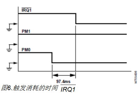
It took 97.4 ms from entering PSM2 mode to trigger the pin. Set low  when power theft is detected . Summary
ADE9078 is a newly designed metering AFE with high dynamic range and high accuracy. It provides four power modes with the lowest power consumption of 1 μA. ADE9078 consumes only 1.412 mAh energy at most in the state of total voltage loss, which is much lower than the battery capacity of 1.2 Ah. ADE9078 can be used to detect total voltage loss, even if this condition lasts for 7 days.
Previous article:JP cabinet intelligent distribution transformer terminal A9 core board solution
Next article:Smart electricity opens the door to more efficient electricity use in homes and buildings
- Popular Resources
- Popular amplifiers
- Infineon Technologies Launches ModusToolbox™ Motor Kit to Simplify Motor Control Development
- STMicroelectronics IO-Link Actuator Board Brings Turnkey Reference Design to Industrial Monitoring and Equipment Manufacturers
- SABIC further deepens strategic partnership with Boao Forum for Asia
- Using 3.3V CAN transceivers to achieve reliable data transmission in industrial systems
- Nidec Precision Testing Technology will be exhibited at SEMICON Japan 2024
- HARTING and TTI announce strategic partnership now extended to Asia
- Samtec Connector Science | Connecting Artificial Intelligence in Smart Factories
- Advantech and Innodisk collaborate to unlock AMR vision capabilities with AFE-R360 MIPI camera module
- Laird Thermal Systems Announces New Line of Micro-Thermoelectric Coolers for Next-Generation Optoelectronic Devices
- Intel promotes AI with multi-dimensional efforts in technology, application, and ecology
- ChinaJoy Qualcomm Snapdragon Theme Pavilion takes you to experience the new changes in digital entertainment in the 5G era
- Infineon's latest generation IGBT technology platform enables precise control of speed and position
- Two test methods for LED lighting life
- Don't Let Lightning Induced Surges Scare You
- Application of brushless motor controller ML4425/4426
- Easy identification of LED power supply quality
- World's first integrated photovoltaic solar system completed in Israel
- Sliding window mean filter for avr microcontroller AD conversion
- What does call mean in the detailed explanation of ABB robot programming instructions?
- STMicroelectronics discloses its 2027-2028 financial model and path to achieve its 2030 goals
- 2024 China Automotive Charging and Battery Swapping Ecosystem Conference held in Taiyuan
- State-owned enterprises team up to invest in solid-state battery giant
- The evolution of electronic and electrical architecture is accelerating
- The first! National Automotive Chip Quality Inspection Center established
- BYD releases self-developed automotive chip using 4nm process, with a running score of up to 1.15 million
- GEODNET launches GEO-PULSE, a car GPS navigation device
- Should Chinese car companies develop their own high-computing chips?
- Infineon and Siemens combine embedded automotive software platform with microcontrollers to provide the necessary functions for next-generation SDVs
- Continental launches invisible biometric sensor display to monitor passengers' vital signs
- PCB development history
- Find a wireless positioning expert
- Why open source hardware needs open source software
- UCC24624 Synchronous Rectifier Controller Improves LLC Resonant Converter Efficiency
- 4572.C2000 CLA FAQ V1.0
- Goodbye 2019, Hello 2020" + Transformation from Senior Technical Engineer to Purchasing and R&D
- Rapidly and accurately evaluate high-speed ultra-large-scale parallel multiplication and addition circuit combinational logic resources
- The impact and value of collision avoidance systems in smart cars on society
- Share a set of information about RH850/D1L/D1M vehicle instrument chips!
- RISC-V MCU Development (Part 7): Code Debugging

 ISO113/2K5


 京公网安备 11010802033920号